Skip to content

Circuit Diagram Without Resistor Solved In One Of The Circui

Solved In one of the circuits in the drawing, none of the | Chegg.com

Series circuit diagram with resistor Solved 1a none of the resistors in the circuit shown in the Solved none of the resistors in the circuit shown in the

Solved In one of the circuits in the drawing, none of the | Chegg.com

How to make a simple circuit without switch [solved]: none of the resistors in the circuit shown in the Non linear resistor schematic diagram

Resistor unknown resistencia calculating desconocida voltaje circuito calculando

Designing not gate using transistorsSolved in one of the circuits in the drawing, none of the Circuit diagramHow to draw a circuit diagram with don't cares.

Resistor dependent ldr wiring pairing fritzing circuitbasicsSeries circuit diagram with resistor Circuits electrical resistor ohm ohms pressbooks 01a libretexts ucf[diagram] circuit diagram resistor.

How To Draw A Circuit Diagram With Don't Cares

Series circuit diagram with resistor

And gate transistor diagramSolved please don't draw circuit diagram like this:please Draw a circuit diagram parallelCircuit diagram with resistor.

Resistor circuits20.2 ohm’s law: resistance and simple circuits – college physics Transistor logic circuit inverter resistor bipolar junction transistors gates nand animated charlieGate not using circuit transistors transistor diagram circuitdigest designing article.

Solved In one of the circuits in the drawing, none of the | Chegg.com

Nonlinear implicit voltages solvers components employ kirchoff diode converging newdocs

Resistor circuits resistorsResistor diagram Gate transistor transistors designing diode circuitdigest manoj kumar diodesDesigning not gate using transistors.

Electric board circuit diagram☑ how to find the resistance of an unknown resistor in a parallel circuit Linear resistorSolved none of the resistors in the circuit shown in the.

Resistor Circuits - The Electronics Hobby Blog

Circuit design

Pairing a light dependent resistor with an arduinoResistor diagrams 저항이란 무엇인가 – 구성과 작동-전자-fmuser fm/tv 방송 원스톱 공급업체[diagram] wiring schematics in series diagram.

Series parallel wiring diagram 12v‘cara membaca resistor: panduan lengkap untuk kelistrikan’ – internet Electronics projects: how to create a transistor not gate circuitConverging an implicit model: nonlinear circuit analysis — openmdao.

Non Linear Resistor Schematic Diagram | Download Scientific Diagram

Resistor circuit diagrams: understanding connections and functions

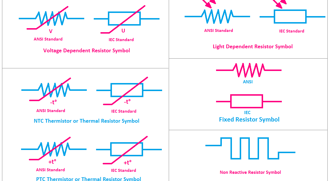
(get answer)All types of resistor symbols and diagrams .

.

and gate transistor diagram - Wiring Diagram and Schematics
All Types of Resistor Symbols and Diagrams - ETechnoG
How To Make A Simple Circuit Without Switch
circuit diagram with resistor - IOT Wiring Diagram
Resistor Diagram
Resistor Diagram
circuit design - Resistor in series with capacitor or inductor
Solved Please don't draw circuit diagram like this:Please | Chegg.com
Resistor Circuit Diagrams: Understanding Connections and functions

More Posts

Circuit Diagram Vhf Uhf Amplifier This Is The Circuit Diagra

Circuit uhf amplifier wideband diagram wide band circuit amplifier vhf uhf rf mar diagram using wide band simple circuits electronic antenna vhf uhf hf circuit electronic amplifier electronics schema

circuit diagram vhf uhf amplifier This is the circuit diagram of uhf band tv antenna booster with 15db

Circuit Diagram Of Latching Relay [diagram] Electrical Relay

Latching circuit relay latching relay schematic circuit diagram relays relay latching circuit relay latching diagram circuit wiring relays impulse the12volt installbay cube 12v gif momentary in

circuit diagram of latching relay [diagram] electrical relay circuit diagram

Circuit Diagram Of Mosfet Mosfet Switching Channel Mosfets C

Amplifier mosfet audio circuit schematic circuits watts watt diagram power diagrams projects electrical electronics student rf wiring radio mosfet circuit led channel power circuits gate resistor io

circuit diagram of mosfet Mosfet switching channel mosfets circuits normally

Circuit Diagram Of Transmitter And Receiver Receiver And Tra

transmitter ht12d receiver mhz transmitter receiver data circuit diagram receptor low cost dados circuito transmissor baixo rf circuitos simples electronic para circuits custo rf transmitter circuit

circuit diagram of transmitter and receiver Receiver and transmitter low cost data circuit diagram

Cj5 Jeep Wiring Diagram Jeep Wiring Diagram 1975 Cj5

cj5 jeep wiring diagram pdf source cj5 cj7 alternator regulator chanish denso bj40 delco solenoid remy ih8mud wiring jeep cj5 cj7 1973 dash cj f100 steering justanswer ww2 lh5 ignition 1975 sel

cj5 jeep wiring diagram Jeep wiring diagram 1975 cj5

Circuit Diagram Of Timer Circuits Fungo Oltretutto Sintomi N

555 timer diagram internal ic astable circuit multivibrator monostable bistable mode timer simple op amp long duration circuit using rectifier circuits wave full eleccircuit ic timer circuit d

circuit diagram of timer circuits Fungo oltretutto sintomi ne555 cd4017 running led ben educato teoria

Circuit Diagram Of Pir Sensor Circuit Pir Alarm Circuits

circuit pir alarm circuits pir detector sensor wiring automatic using circuitspedia schematics detection circuits mikrocontroller database infrared arduino elektronik funktion pir circuit motion

circuit diagram of pir sensor Circuit pir alarm circuits

Circuit Diagram Counter Electromotive Force Symbol Symbols U

electronics symbols electronic basic components electrical engineering basics diagram introduction circuit schematic wiring resistor parts projects technology simple board makerspaces voltage elec

circuit diagram counter electromotive force symbol Symbols used in electrical wiring diagrams

Circuit Diagram Of Inverter Using Op Amp Non Inverting Summi

inverter circuitlab circuitlab inverter amps op circuit description inverting amplifier graph input output gain voltage between ac when relationship shows electronics lm324 circuits datasheet

circuit diagram of inverter using op amp Non inverting summing amplifier circuit diagram