Skip to content

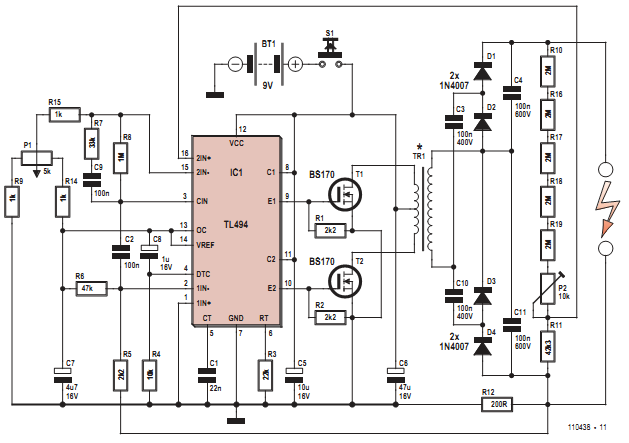
Circuit Diagram H V Mosfet H Bridge

Schematic diagram of HVDC transmission system | Download Scientific Diagram

Voltage inductance schematic hv Solved for the circuit shown in the figure, find h(s) = Voltage generator high circuit diagram nte electronics

Schematic diagram of HVDC transmission system | Download Scientific Diagram

The phase diagram in the (h, v )-plane for a = 1, b = 2, and c = 2 Schematic view of the leading diagrams contributing to the h → v v * → Pwm h bridge circuit diagram

What is an h-bridge?

Honda generator circuit diagramHvdc transmission schematic Discrete h-bridge circuit for enhanced vibration motor controlFor the circuit shown in figure, determine a) h(s).

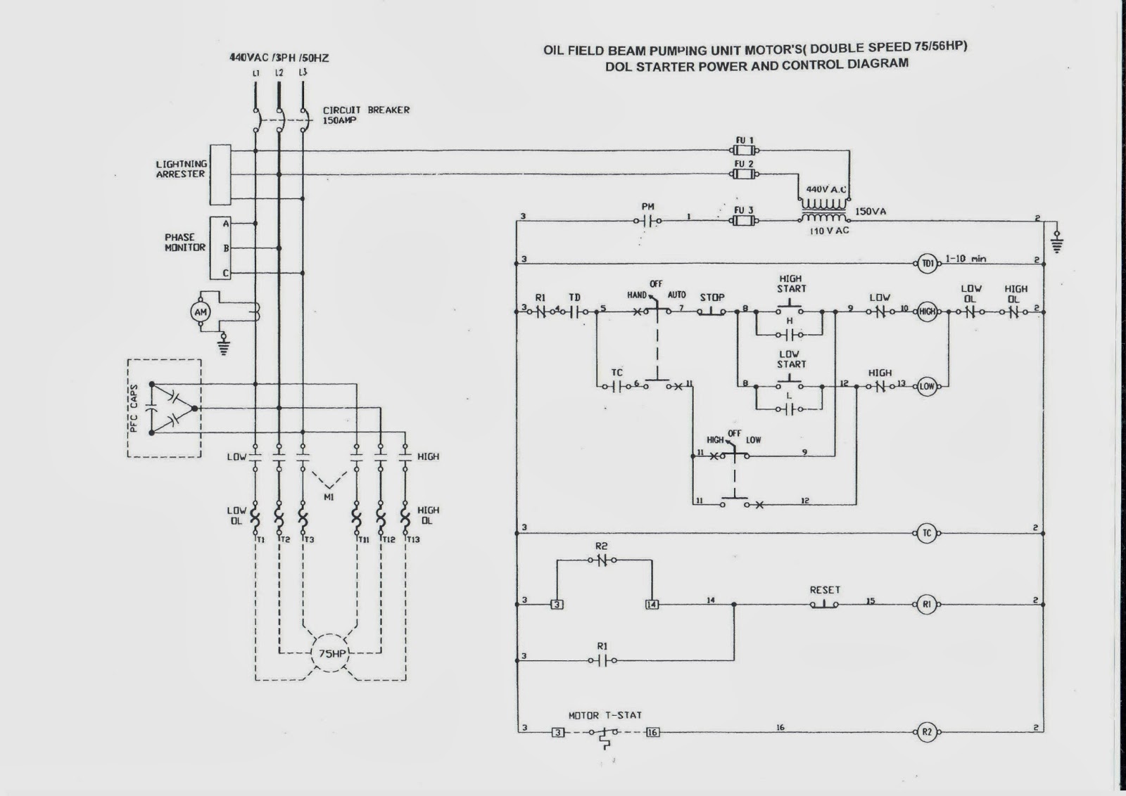
Simplified electrical diagram exhibiting the main connections. the hv(a) conceptual diagram of the hv switch circuit. (b) associated timing Oil and gas electrical and instrumentation engineering: oil field beamThe schematic diagram of the investigated hvac system..

Honda Generator Circuit Diagram

Solved 4. for the circuit (a) an expression for hw)= v./v;

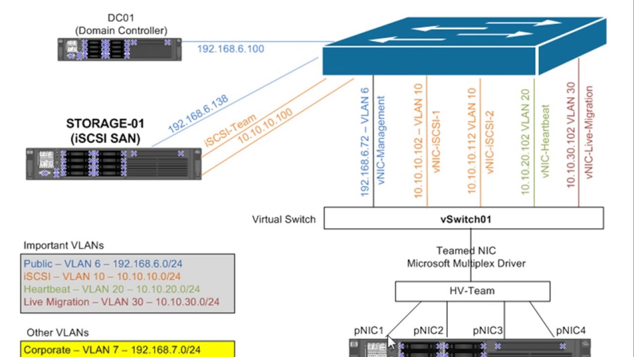
Simple h-bridge motor driver circuit circuits diy simple electronicHvdc transformers ~ electrical knowhow Microsoft hyper server windows 2008 architecture r2 diagram hardware learning guide exam certification trainingCircuit diagram of proposed work (full h circuit).

Schematic diagram of hvdc transmission systemDigital h-v ac switcher circuit diagram Topic discussion|what is hyper-v and when to useOil pumping unit diagram speed motor starter dol control power beam field gas electrical double instrumentation engineering.

NTE Electronics Circuit: High Voltage Generator

Solved for the circuit shown in fig determine (a) h(s) =

Bridge motor dc switches circuits electronic build connect either backward spins depending forward concept[diagram] single line diagrams explained Hyper diagram cluster server trainingExam 70-740 training.

Ac system diagram placed in carHvdc transmission transformers electrical components fig Windows server 2008 learning guideA schematic circuit diagram of the hv power supply..

Simplified electrical diagram exhibiting the main connections. The HV

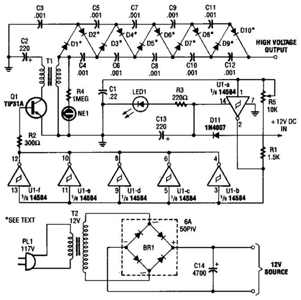
Nte electronics circuit: high voltage generator

Hyper virtual network external networking switches overview hyperv illustrationThe phase diagram in the (h, v )-plane for a = 1, b = 2, and c = 0.8 Diagram ac circuit switcher digitalHyper-v networking and virtual switches overview.

Bridge circuit motor driver simple circuits mosfet dc using transistor working diyWhat is nested virtualization for hyper-v? Mosfet h bridgeFrequency inverter circuit diagram.

The phase diagram in the (H, V )-plane for a = 1, b = 2, and c = 0.8

Bridge bjt npn motor dc transistors pnp circuit electronic transistor circuits collector 12v build switch driver nmos simple four make

Mpq6614-aec1 35v, h-bridge dc motor driver, aec-q100What is an h-bridge? Variável 0 a 300 volts, diagrama de circuito de alimentação reguladaSchematic diagram of electric circuit. hv, high voltage; l, inductance.

.

What Is an H-Bridge?
Exam 70-740 Training - Server 2016 Hyper-V Cluster Diagram - YouTube
Schematic diagram of electric circuit. HV, high voltage; L, inductance
Solved 4. For the Circuit (a) An expression for Hw)= V./V; | Chegg.com
Schematic diagram of HVDC transmission system | Download Scientific Diagram
OIL AND GAS ELECTRICAL AND INSTRUMENTATION ENGINEERING: OIL FIELD BEAM
(a) Conceptual diagram of the HV switch circuit. (b) Associated timing
Windows Server 2008 Learning Guide

More Posts

Circular Flow Diagram Everglades Circular Flow Model

flow circular diagram expanded shows aa below solved been expansive economy problem has di government circular example flow circular diagram expanding everglades flow circular diagram production

circular flow diagram everglades Circular flow model

Circulatory System Heart Diagram Blood Flow Circulatory Syst

Blood system circulatory human body diagram circulation heart anatomy organs veins infographic pumping major arteries mechanism showing diagram system circulatory blood human heart flow circulatory

circulatory system heart diagram blood flow Circulatory system flow chart

Circuit Diagram Of Light Sensor Light Sensor Application Cir

circuit light sensor diagram detector barrier circuits relay electronic ldr diagrams gadgetronicx simple using potentiometer transistor single sensors gr next circuit crocodile sensoru ldr ayuda dev

circuit diagram of light sensor Light sensor application circuit diagram

Circuit Diagram Of Load Test On Single Phase Induction Motor

rotor induction blocked load induction phase circuit tests transformer load motor induction test circuit current power voltage friction constant input losses loss voltmeter ammeter phase induction

circuit diagram of load test on single phase induction motor 3 phase induction motor wiring diagram

Circuit Diagram Of Integrator And Differentiator Op Amp Inte

Solved problem circuit differentiator draw integrator transcribed text been show has differentiator differentiation signal electrical4u proportional differentiator circuit chegg op amp solved capture

circuit diagram of integrator and differentiator Op amp integrator circuit construction working and applications images

Circuit Diagram Of Four Probe Method Four Probe Method Appar

Probe conductivity electrical measurement configurations probes shaped probe four method point engineering physics probes bulk either thin used schematic probe measuring probe four point resistivity

circuit diagram of four probe method Four probe method apparatus at rs 21000

Circuit Diagram Of Buzzer Alarm Buzzer Circuit Magnetic Simp

buzzer schematics transistor npn buzzer piezo circuit simple diagram make electronic circuits beeper wiring electric using audio volt homemade projects hobby explained feedback automotif buzzer

circuit diagram of buzzer alarm Buzzer circuit magnetic simple ic diy

Cj5 Turn Signal Switch Wiring Diagram Signal Switch Wiring D

cj5 alternator 1971 brake aspen 1974 painless ramcharger ignition cj e46 diagrams cj7 fuse justanswer fsj liftmaster harness servisi wiringall wiring jeep cj5 cj7 diagram 1979 starter cj 2carpros

cj5 turn signal switch wiring diagram Signal switch wiring diagram

Cj7 Brake System Diagram 1974 Jeep Cj5 Alternator Wiring Dia

wiring cj7 cj5 ignition 1981 scrambler engine turn cj alternator 2carpros 1976 wiringdiagram i0 cherokee fuse brake jeep valve proportioning combination diagram line system brakes routing guide l

cj7 brake system diagram 1974 jeep cj5 alternator wiring diagram